What is the difference between DC, servo and stepper motors?
- Vagif Aliyev
- Dec 30, 2021
- 4 min read
Updated: Oct 15, 2023

The right engine for different applications depends on some design criteria, such as position accuracy requirements, price, drive power, torque, and acceleration requirements. In general, motors such as DC, servo and stepper motors are best for a variety of applications. However, the stepper motor is well suited for high holding torque and lower acceleration applications. Many do not understand that there is a big difference between a DC motor, a servo motor and a stepper motor. You can read this article to know the differences between these three engines!
The difference between a DC motor, a servo motor and a stepper motor:
Choosing between a DC motor, servo and stepper motors can be a daunting task, including balancing many design factors, namely price, speed, torque, acceleration, as well as the drive circuit, all of which play an important role in choosing the best one.
DC motors - DC Motor is a two-wire continuously rotating motor with two wires of power and ground. When the supply is applied, a DC motor will start rotating until this power is released. Most DC motors operate at high revs per minute (RPM), e.g. cooling system or radio-controlled car tires used in computers for cooling.

DC motor speed can be controlled using PWM (pulse width modulation) technique, a fast pulse technique of ON and OFF power. The percentage of time spent cycling with the ON / OFF ratio determines the engine speed. For example, if the power is 50% controlled, then the DC motor will rotate at half the speed of 100%. Each pulse is so fast that the engine spins without stopping!
Servo motors - Generally, a servo motor is a combination of four parts, namely a DC motor, a control circuit, a gear set, and also a potentiometer, usually a position sensor. The condition of a servo motor can be controlled more accurately than typical DC motors, and there are generally three wires, such as power, GND, and control. Power is supplied to these motors continuously, and the control circuit of the servo motor changes the traction to control the servo motor. These engines are designed for more precise tasks that require the engine position to be precise, such as moving the robot arm over a certain range or steering on a boat or robot leg.

These motors are not as easily alternative as a standard DC motor. In its place, the angle of rotation is partially equal to 1800. Servo motors receive a control signal indicating the o / p position and apply power to the DC motor until the shaft moves to the exact position determined by the position sensor. PWM (pulse width modulation) is used to control the signal of the servo motor. However, unlike DC motors, this is a positive pulse cycle that controls the position of the servo shaft slightly more than the speed. The value of the neutral pulse depends on the servo holding the servo motor shaft in the middle position. Increasing the pulse value will cause the servo motor to turn counterclockwise, and a shorter pulse will turn the shaft counterclockwise. The servo control pulse is usually repeated every 20 ms, and although this means staying in a similar position, it basically tells the servo motor where to go. When the servo is ordered to move, even if an external force pushes against it, it will move to that position and take that position. The servo motor will struggle to move out of this position, the maximum resistance force that the servo motor can use is the torque of that servo.
Step motors - A stepper motor is basically a servo motor that uses a different motorization method. In cases where the motor includes a continuously rotating DC motor and a combined control circuit, stepper motors use multiple electromagnets placed around central equipment to describe the position. The stepper motor needs an external control circuit to provide power to each solenoid separately and to keep the motor shaft open. When controlled by electromagnetic force, it pulls the teeth of the equipment and supports them, slightly different from the next electromagnetic "B". When ''A'' is turned off and ''B'' is turned on, the device rotates slightly to match ''B'' and everywhere in the circle, energizing each electromagnetic turn around the device and cutting off the energy to make the rotation. Each transition from one electromagnet to another is called a "step" and therefore the motor is activated with a predetermined step angle of 3600 rpm.
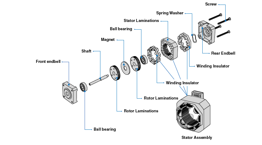
These motors are used in two types, namely unipolar and bipolar. Bipolar motors are the most robust type of engine and generally have 4 or 8 drives. They have two rows of electromagnetic coils, and the stairs are obtained by changing the direction of current in the coils. Unipolar motors are known to have 5 wires, 6 wires or even 8 wires, and also have 2 windings, but each has a central tap. These motors can step in the opposite direction of the current in the coils and simplify the electronics. However, since these cranes are used to power only half of each roll at a time, they typically have less torque than bipolar. The design of stepper motors can provide a constant holding torque without the need for an activated motor, provided that the motor is used within its limits and that positioning errors do not occur, as these motors have predetermined conditions.
Pros and cons of DC, servo and stepper motors:
DC motors are mainly fast and continuous rotary motors used for everything that needs to be rotated at high revs per minute (RPM). For example; car tires, fans, etc.
Servo motors are high torque, fast, precise rotation at a limited angle. In general, a high-performance alternative to stepper motors, but a more complex installation with PWM regulation. Suitable for robotic arms / legs or steering control, etc.
Stepper motors are slow, easy to install, precise rotation and control. The advantage of position control over other motors, such as servo motors, is that when the motors require a feedback mechanism and a rear-wheel drive to control the position, this motor has position control with the nature of rotation with fractional attachments. Suitable for 3D printers and related devices where position is important.


Comments