Rotary Encoder
- Vagif Aliyev
- Jan 9, 2022
- 5 min read
Updated: Feb 23, 2025

An encoder is a device used to change one data format to another. In other words, a device used to detect and convert mechanical motion into an o / p signal with analog or digital code. Encoders are available in two configurations, linear and rotary, but the most commonly used configuration is rotary. Thus, the rotary encoder is developed in two main forms as an absolute encoder and a incremental encoder. Most rotary encoders are made of plastic or glass threaded disk, because the radial lines in each path will distort the beam between the photoemitter-detector pair to generate digital pulses.
What is a rotary encoder?
A rotary encoder (shaft encoder) is an electromechanical device used to change the motion of a shaft, the angular position of a rotating shaft. This encoder generates an electrical signal based on rotating motion, such as analog or digital. These include robotics, industrial controls, photo lenses, track balls, optomechanical mice, controlled stress rheometers, and more. are used in various applications that require control or monitoring, such as computer input devices. It can be implemented using various parts such as rotary encoder design, rotating disk including code disk or labels, light source including electronic board, receiver IR photosensor, optical-mechanical block including gears, electronic board with digital interface converters and signal processors.
Contact construction:
The combination configuration of a rotary encoder includes five sections, and you can review them below.
Pin1 (GND): This is a ground contact.
Pin2 (VCC): This is a positive voltage supply pin that operates at 3.3 V or 5 V.
Pin3 (SW): This is an active down button. After pressing the button, the voltage will be lower.
DT (Output B): This is similar to clock output; but lags behind the clock with a 90 ° phase shift. Thus, this output can be used to determine the direction of rotation.
CLK (Output-A): This is the main output signal used to determine the amount of rotation. Each time the button on the encoder will go through a single plug in any direction. The 'CLK' output will go through a high circuit and then go down.
Rotary encoder operation:
We can observe how square wave signals are generated in a rotary encoder. In general, this encoder consists of a disk located at equal distances from the contact zones. The connection of these contact zones can be made to the common pin-C and to the other two separate contact pins, such as A and B, shown below.

The disc in this encoder will begin to rotate slowly, and both pins, such as A and B, will be in contact through a common pin. Thus, the creation of a two-square wave output signal can be performed accordingly. Here, the rotating position can be determined using either of the two outputs. But if we want to decide on the direction of rotation, then we need to consider both signals at the same time. We can observe that the two o / p signals are shifted 90 degrees apart from each other. If this encoder rotates clockwise, output A will be after output B. Each time we count the steps, the signal will change from low to high or from high to low. Then we can observe that two output signals, A and B, have opposite values. If this encoder rotates counterclockwise, both output signals will have the same values. With this in mind, we can simply program the controller to study the position of the encoder and the direction of rotation.
Types of rotary encoder:
These encoders are divided into two types.
Incremental Type
Absolute Type
Incremental rotary encoder - An incremental rotary encoder is used to provide low and high wave sequence. These waves will determine the movement of the position. These types of encoders will provide a sequence of periodic signals in the form of pulses due to the rotational movement of the shaft. The speed of an object can be measured by counting the pulse for a while. These pulses can be calculated simply from the reference point, otherwise it is possible to determine the distance covered. The incremental rotating encoder generates two digital o / p signals, where the phase connections between these two sensors will decide to rotate the encoder clockwise counterclockwise. Thus, using this encoder, the position can simply be determined. After generating a light emitting diode light, it passes through a crystal clear disk. Once this light signal is received by the photosensor, a sinusoidal signal can be generated, which is converted into a pulse layer or a square wave. The pulse wave will transmit a signal to create the preferred function, which can be transmitted to the rotating meter.
Absolutely rotary encoder - An absolutely rotary encoder is used to store position information after power is removed from the rotary encoder. The position of this encoder is available immediately after power is applied. This encoder contains different code loops through different binary weights that provide the information word to indicate the absolute position of the rotary encoder in each circuit. Thus, this type of encoder is also called an absolute encoder. The multi-turn absolute rotator encoder mainly consists of additional gears and code wheels. A high-resolution wheel can measure lower fractional rotation, and a smaller gear code can record full shaft cycles.
Connection diagram of a rotary encoder:
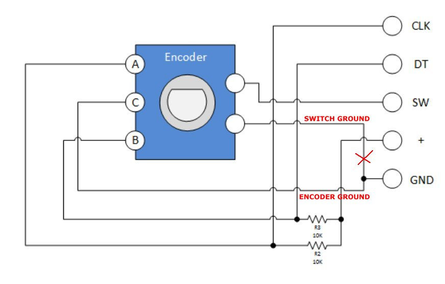
The interface of the rotary encoder with the Arduino Uno can be done as described below.
Connect the VCC pin of the encoder to the 5V pin of the Arduino
Connect the GND pin of the encoder to the GND pin of the Arduino
Connect the CLK pin of the encoder to the D3 pin of the Arduino
Connect the CLK pin of the encoder to the D4 pin of the Arduino
Once the connections are established, connect the Arduino Uno board to your computer.
Download the encoder to the Arduino Uno board. Click on tools-> select serial monitor and start on serial monitor. So you can now start turning the encoder shaft and observe the print output on the serial monitor. After turning the shaft clockwise, the serial monitor will print the number of the encoder.
Advantages:
These are reliable
Accurate
Resolution is high
Size is compact
Less cost feedback
Integrated electronics
Can be included in existing applications
Disadvantages:
Sensitive to oil, dirt & dust contaminants
Direct light source interface
Applications:
They are used where speed, direction, acceleration and rotational speed control are required.
They are used in various industries such as material processing, packaging and conveyor.
In the field of automation, these encoders are used as sensors for speed, angle, acceleration and position.
These are used to measure linear motion using gears, shafts, cable pulls, or measuring wheels.
These encoders are used in industries to convert mechanical input to electrical signals using tachometers, meters, PLC systems, and personal computers.
They are used in packaging, assembly machines, display systems, printers, CNC machines, test machines, robotics, textiles, motor feedback, medical equipment, drilling and labeling machines.
How accurate is the rotating encoder?
The accuracy of rotating encoders can usually be expressed in degrees or arc seconds.
What is the most accurate encoder?
The absolute optical shaft encoder is the most accurate because it has a typical accuracy of 0.18 degrees (10.8 arc minutes) and a maximum accuracy of 0.25 degrees.


Comments